A Metal 3d Printer is not simply a larger version of a plastic printer. It is a controlled manufacturing system that transforms metal powder or wire into functional components. Depending on the process, a laser, electron beam, or directed energy source melts material layer by layer. Each layer may be thinner than a human hair. The result can be a complex bracket, medical implant, turbine component, or lightweight aerospace structure.
Terry Wohlers, a respected additive manufacturing analyst, once stated, “3D printing is not just for prototyping anymore.” That observation still matters. Modern metal printing increasingly supports production, but it does not remove every manufacturing challenge. Engineers must manage powder quality, thermal distortion, residual stress, surface roughness, and machine calibration. A printed part may look excellent while hiding internal defects. That possibility deserves serious attention.
The working process begins with a digital 3D model. Specialized software slices the model into hundreds or thousands of layers. The printer then deposits or spreads metal material before applying concentrated energy. After printing, the part may require heat treatment, support removal, machining, polishing, and inspection. Nothing is truly finished when the printer stops.
This article explains what happens inside a Metal 3d Printer, from digital preparation to final testing. It also examines major printing technologies, suitable materials, operating costs, and practical limitations. Some claims about metal printing sound impressive. Real experience is usually less tidy. Reliable results depend on process control, verified data, skilled operators, and patient evaluation.
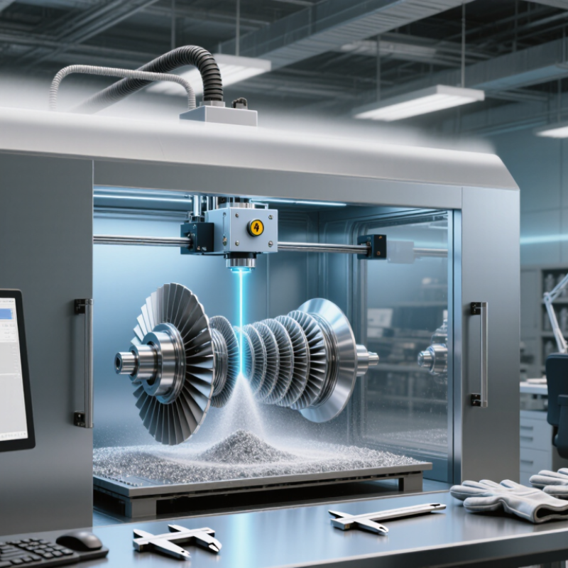
A metal 3D printer is a machine that creates solid metal parts from digital designs. It builds each part layer by layer, rather than cutting it from a larger block. The process may use metal powder, metal wire, or a metal-filled binder. Heat, usually from a laser or electron beam, melts or joins the material. Some systems bind the powder first, then use a furnace to strengthen the part.
The printer needs more than a 3D file. Operators must control layer thickness, energy levels, material flow, and cooling conditions. These settings affect strength, surface texture, and internal defects. A printed part often needs support removal, heat treatment, machining, or polishing. The process sounds precise. It is not effortless. Small changes in powder quality or temperature can cause warping, cracks, or weak areas. Experienced technicians inspect parts with measurements and suitable testing methods.
Tips: Choose a material that matches the part’s working conditions. Check powder handling procedures and ventilation requirements. Keep the build chamber clean. Record every setting during production. This makes problems easier to trace. Do not judge quality by appearance alone. A smooth surface can still hide internal flaws, while a rough surface may be corrected later. Careful inspection remains essential, especially for parts exposed to heat, pressure, or repeated movement.

A metal 3D printer builds parts layer by layer from digital design data. Its feedstock may be powder, wire, or metal-filled filament, depending on the process. For material selection, the real question is not, “Can it print metal?” It is, “Can it control this alloy reliably?”
Common choices include stainless steel, tool steel, aluminum alloys, titanium alloys, nickel alloys, and cobalt-chromium. Each behaves differently under heat. Stainless steel usually offers balanced strength and corrosion resistance. Aluminum is light, but its high thermal conductivity can complicate melting and distortion control. Titanium supports strong, lightweight components, though oxygen exposure demands careful handling. Nickel alloys tolerate high temperatures, making them useful for demanding industrial environments. Copper alloys remain challenging because they reflect energy and remove heat quickly.
In practice, I would check powder size, moisture, oxygen content, flowability, and recycling limits. A smooth powder spread matters. Wire-based systems need consistent diameter and clean storage. The printer also needs a validated temperature profile for the selected alloy. Small changes can create pores, cracks, rough surfaces, or weak bonding. Post-processing may include heat treatment, support removal, machining, and surface finishing. Material data sheets help, but test coupons reveal what the machine actually achieves. That gap deserves attention. A material may be printable yet unsuitable for a precise, certified part. I would avoid overconfidence and repeat testing before changing the design.
A metal 3D printer builds parts layer by layer from digital design data. The process begins with a carefully prepared CAD model. Engineers check wall thickness, overhangs, holes, and likely distortion before slicing the model into thin layers. Small mistakes here can become expensive defects later.
The printer receives metal powder or wire as feedstock. A controlled energy source then melts selected areas according to each sliced layer. In powder-bed systems, a recoater spreads a thin powder layer across the build platform. A laser or electron beam traces the required shape. The platform lowers slightly, and the cycle repeats. Inert gas or a vacuum helps limit oxidation during printing. The part grows slowly.
Temperature control matters greatly. Uneven cooling can create warping, pores, or internal stress. Support structures may hold delicate features and improve heat removal, although they require later cutting. After printing, technicians remove loose material, separate the part, and apply heat treatment when necessary. Machining can refine holes and critical surfaces. Inspection may include dimensional measurement, visual checks, and non-destructive testing.
In practice, the process is powerful but not forgiving. A clean powder does not guarantee a perfect part. Settings, geometry, moisture, and operator judgment all influence results. I would not treat a successful first build as proof of reliability. Process records and repeated testing remain essential.
| Process Stage | What Happens | Key Materials or Inputs | Typical Data or Range | Result |
|---|---|---|---|---|
| 1. Digital Design | A three-dimensional CAD model is converted into a mesh and positioned in the build volume. | CAD software, STL or 3MF file, build-orientation settings | The model is divided into horizontal layers before printing. | A machine-readable build file containing tool paths and process parameters |
| 2. Metal Feedstock Preparation | The printer receives metal powder, metal wire, or metal-bound filament, depending on the technology. | Stainless steel, aluminum, titanium, nickel alloys, tool steel, or other qualified metals | Powder-based systems commonly use particles about 15–63 micrometers in diameter; exact specifications vary. | Consistent feedstock suitable for controlled layer deposition |
| 3. Build-Plate Preparation | A metal build plate is installed, leveled, and often heated or surface-treated to improve adhesion. | Build plate, fixtures, calibration tools, inert process environment | The build plate provides mechanical support and helps reduce distortion during manufacturing. | A stable foundation for the first printed layer |
| 4. Layer Deposition | A thin layer of feedstock is spread or deposited over the build area. | Recoater blade, powder hopper, wire feeder, or filament drive system | Common powder-bed layer thickness is approximately 20–60 micrometers; larger values may be used for faster production. | A uniform layer of metal feedstock ready for selective bonding |
| 5. Selective Melting or Bonding | A heat source follows the programmed tool path and melts, sinters, or bonds selected regions of the layer. | Laser, electron beam, arc, or heated nozzle, depending on the process | Laser and electron-beam systems can locally melt metal at temperatures above the alloy melting point. | A solidified cross-section that forms part of the final component |
| 6. Recoating and Repetition | The platform moves by one layer height, a new layer is added, and the heat source repeats the programmed pattern. | Motion system, sensors, control software, protective gas or vacuum chamber | The cycle continues for hundreds or thousands of layers, depending on part height. | A three-dimensional near-net-shape metal part |
| 7. Atmosphere Control | The process environment is controlled to limit oxidation and contamination while the metal is heated. | Argon or nitrogen for many powder-bed and directed-energy systems; vacuum for some electron-beam processes | Oxygen levels are commonly controlled to low concentrations, with the required limit determined by the material and process. | Improved melt-pool stability and reduced oxidation risk |
| 8. Cooling | The printed part cools in a controlled manner after the final layer is completed. | Build chamber, inert gas circulation, thermal monitoring | Cooling time may range from several minutes to many hours, depending on part size, material, and machine settings. | A cooled part that can be safely removed for post-processing |
| 9. Part Removal | The component is separated from the build plate, and temporary support structures are removed. | Band saw, wire electrical-discharge machining, milling, or manual tools | Support structures are often required for overhangs, heat conduction, and part stability. | A free-standing printed component with residual support material removed |
| 10. Heat Treatment | Thermal processing can relieve residual stress and adjust the material microstructure. | Stress-relief, annealing, hot isostatic pressing, or solution and aging treatments | The required temperature and duration depend on the alloy and target properties. | Improved dimensional stability, density, ductility, or fatigue performance |
| 11. Surface Finishing | Machining, blasting, tumbling, polishing, or chemical treatment improves dimensional accuracy and surface quality. | CNC machining, abrasive media, polishing tools, finishing chemicals | As-built surfaces are typically rougher than machined surfaces; the final finish depends on orientation and process settings. | A smoother surface and tighter dimensional tolerances |
| 12. Inspection and Qualification | The finished part is checked for dimensions, internal defects, density, surface condition, and mechanical performance. | Calipers, coordinate-measuring machines, computed tomography, microscopy, tensile testing | Inspection may include dimensional checks, density verification, and testing against the required design standard. | A documented assessment of whether the part meets its intended requirements |
A metal 3D printer turns digital geometry into a metal component by adding material in thin layers. The machine follows sliced design data, forms each layer, and joins it through heat, pressure, or a chemical reaction. Its practical value appears in internal channels, lightweight lattices, and shapes that machining may struggle to produce. Yet the printer is only one part of the process. Powder quality, calibration, atmosphere, and finishing strongly affect strength and accuracy.
Powder bed fusion spreads fine metal powder across a build platform. A laser or electron beam selectively melts each cross-section. It suits detailed parts and complex passages, but residual stress may cause distortion. Parts often need support removal and heat treatment.
Directed energy deposition feeds wire or powder into a focused heat source. It can build large features, repair worn surfaces, or add material to existing components. Its deposition path is flexible, although surface finish usually needs machining.
Binder jetting deposits liquid binder onto powder, shaping a fragile “green” part. The part is then debound and sintered, which can shrink it noticeably. That shrinkage is manageable with validated process data, not guesswork.
Sheet lamination joins thin metal sheets through bonding and selective cutting. It can be economical for certain geometries, but layer interfaces may limit performance.
In practice, engineers choose by part size, tolerance, alloy, production volume, and inspection requirements. No method is perfect. A promising design may still fail if supports, thermal behavior, or finishing were underestimated. Small test coupons and dimensional checks reveal those weaknesses early.
A metal 3D printer builds parts layer by layer from powdered or wire-based metal. In powder-bed systems, a focused heat source melts selected areas, then a recoater spreads fresh powder. The process repeats until the digital design becomes a solid component. Operators manage shielding gas, temperature, calibration, and powder handling. The details matter.
Its strongest benefit is design freedom. Engineers can create internal channels, lattice structures, and lightweight shapes that conventional machining may struggle to produce. This can reduce part count and shorten assembly work. Metal printing also supports rapid iteration. A revised component can move from CAD data to a test part without new cutting tools. For low-volume production, that flexibility may offset higher equipment and preparation costs. Some printed alloys can deliver useful strength, heat resistance, or corrosion resistance after proper treatment. Yet results depend heavily on orientation, support design, and post-processing.
The limitations are substantial. Machines and metal powders are expensive, while qualified operators need specialized training. Build times can be long, especially for large parts or dense structures. Surfaces often show visible texture, so machining, polishing, or heat treatment may follow. Tiny pores, distortion, or residual stress can appear if parameters drift. Inspection is not optional. Testing may include dimensional checks, imaging, and mechanical sampling, depending on the part’s risk. In practical evaluations, teams often find that printing freedom encourages overcomplicated designs. A simpler geometry may be cheaper, stronger, and easier to verify.
Typical layer-thickness ranges across common metal 3D printing processes
Metal 3D printers build parts layer by layer from metal powder or wire. Powder bed fusion processes usually create thinner layers and finer details, while directed energy deposition uses thicker layers to achieve higher material deposition rates and support larger repairs or structures. These typical ranges are industry reference values and can vary with the material, machine configuration, and part geometry.